The temperature at Twente Airport has gone up to
33.4° Celsius, which breaks the previous record of 33.3°C on this date
in 2018.
UARTs on the ESP32-S3
Here, I present some information about the low-level operation of the
Universal Asynchronous Receiver/Transmitters (UARTs) on the ESP32-S3. I want to investigate how to use them without enabling
interrupts. I know that for some devices it is possible to enable an interrupt,
causing a flag to be set in the interrupt register, but leave the interrupt
table empty, such that no actual interrupt is generated. An important source of
information is Chapter 26: 'UART Controller' of the Technical Reference Manual. The ESP32-S3 has three UARTs each. The
transmit and receive buffers are taken from a shared 1024 byte region of RAM,
which is divided into 8 blocks of 128 bytes. The buffers start at fixed block.
This makes it possible to have larger transmit and receive buffers for some of
the UARTs, but limiting the buffers for others to zero, which basically
renders the UART (parly) unusable. The buffers of UART2 can be extended to
256 bytes without affecting the operations of UART0 and UART1 with at least
buffers of 128 bytes. (The use of the words 'Reserved' in Figure 26-3 are a
bit misleading, because the RAM regions can be used.) There is a possibility
to transfer large amounts of data by setting up a Direct Memory Access (DMA)
channel in the General Direct Memory Access (GDMA) device, which is described
in Chapter 3: 'GMDA Controller'. However the data goes through a Universal Host Controller Interface (UHCI), which, for example, is used
with USB. The UHCI performs some encoding and decoding to create a 'clean'
data stream surrounded with separators. It is not clear when an UART starts
sending data from the buffer. Is it as soon as a character is entered or only
when the buffer is filled with a certain number of characters and/or when a
certain character (such as a line-feed) is placed in the buffer. In the
reference manual it mentions that setting the UART_FORCE_XON bit
forces the transmitter to send data. This is only set in the
uart_ll_force_xon functions, which is called in
sleep_uart_resume function, which is called when the MCU returns from
sleep mode. This makes me wonder whether this is the only proper usage of it.
For the ESP32-S3 the function uart_ll_force_xon also the sets the
UART_SW_FLOW_CON_EN bit. In the reference manual it says: 'Set this
bit to enable software flow control.' That is maybe something you do not want
to be enabled, because it only works if the other side on the serial connection
also has it enabled with the same characters.
High resolution LCDs with ESP32-S3
ESP-IDF offers various ways to control common LCDs according to the
documentation. For full screen updates, the theoretical maximum frame rate
is determined by the clock frequency multiplied by the bus width and divided by
the product of the number of pixela and the number of bits per pixel. In
practice it can be a bit lower, because most protocols also have some overhead.
Because for high resolution LCD the required screen buffer is usually too
large to fit in RAM, it means that it has to be placed in PSRAM. Depending on
the width of the SPI bus used to access PSRAM, this can pose limits on the
maximum clock frequency. Modifying the buffer in PSRAM also put some limits on
how often one can effectively update the display. ESP-IDF provides only a
limited number of LCD device controller drivers out of the box. More drivers
are available in the ESP Component Registry. A list of drivers that is supported by LVGL is given in Display and touchpad drivers for ESP32 using LVGL. For the ESP32-S3 there are several interfaces that can be used with displays, such
as I2C, SPI, several parallel interfaces, and (the newest) MIPI-DSI, which is
not supported by the ESP32-S3. (It is supported by the ESP32-P4, which is now
declared end-of-life and followed up by ESP32-P4X.) For the parallel
interfaces, I spend some time looking into the LCD controller of the ESP32-S3.
According to Chapter 29 '29 LCD and Camera Controller (LCD_CAM)' of the
Technical Reference Manual it has three parallel output formats: RGB,
MOTO6080, and I8080. There is a choice between 8 or 16 bits data bit. Besides
this, each requires a some other signals, 4 for the RGB, 2 for MOTO6800, and 3
for I8080. The number of bins thus ranges from 10 to 20. (It seems that the
with the LCD_DE signal in Figure 29-5 'LCD Timing (RGB Format)' is
refering to LCD_H_ENABLE.) The maximum data rate is the same for
both bus widths, because it is limited by GDMA and further if YUV-RGB format
conversion is used. If we assume that 2 bytes per pixel are used, it means
that the maximum frame rate for a 800×480 display is 104 without YUV-RGB
format conversion and 78 with. In practice this will be bit lower.
Partial solar eclipse
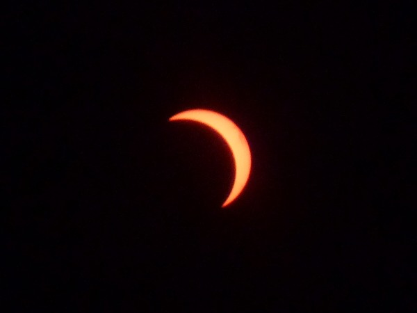
Conny and I watched the partial
solar eclipse from our back garden and from the street in front of our
house. I took several pictures with my Panasonic
Lumix DMC-TZ8 camera where I covered the lens with a pair of
eclipse glasses. Below a crop of the picture I took at 20:17 (ECT) about five
minutes after the maximum of almost 90%. There was a shortage of eclipse
glasses in the Netherlands and I fear that there will be some people having
damaged their eyes with looking into the sun directly. The previous partial
solar eclipse I saw was on May 31, 2003.
34.2° Celsius
The temperature at Twente Airport has gone up to
34.2° Celsius, which breaks the previous record of 34.0°C on this date
in 2025.
Asking ChatGPT
I asked ChatGPT a question about the expression related to convex shapes of hexagons with resulted in the following chat. The question is about equation:
-7(a² + c²) + 2ac + 2n(a + c) + n² - 8l
when n equals to 1 being equal to the square of some integer, say
m. I have been studying the answer. ChatGTP found that if you multiply
the above expression with three you can formulate the question with the
following equation:
4(-6l + 1) - (3(a + c) - 1)² - 12(a - c)² = 3m²
I verified that this indeed the case. The equation can be rewritten into;
-24l + 4 = (3(a + c) - 1)² + 12(a - c)² + 3m²
ChatGTP claims that according to the paper On universal sums of polygonal numbers by Zhi-Wei Sun that for every N greater or equal to zero that
12N+4 can be represented as x²+3y²+3z²
where x is odd. It seems that this is stated in (iii) of Theorem 1.7 in
the paper. Furthermore, ChatGTP reasons that because x is odd, either
y or z must be odd and the other even. From this it is also
possible to state that 24N+4 can be represented with
x²+12y²+3z². Furthermore, ChatGTP shows
that for the integers of x and y, it is possible to show that
a and c are also integers. The value of z is equal to
m.
I figured out that the generic equation for any value of n is
4(-6l + n²) = (3(a + c) - n)² + 12(a - c)² + 3m²
This has solutions if -24l+4n² is equal to 12N+4.
for n=1 this is the case when N=-2l. For n=2 this
is the case when N=-2l+1. For n=3, this is not possible.
For n=4 this is the case when N=-2l+5. For n=5
this is the case when N=-2l+8. For n=6 this is not
possible. For n=7 this is the case when N=-2l+16. I think
this finishes the proof that only for a limited number of cases the perimeter
of the convex shape of hexagons is one larger than the non convex shape of
hexagons.
The temperature at Twente Airport has gone up to
35.6° Celsius, which breaks the previous record of 32.4°C on this date
in 2025.
Walking over the bed of the Usselerstroom
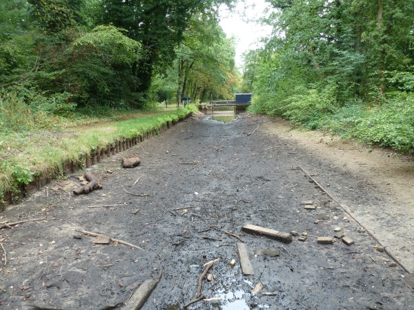
During our walk we noticed that the Usselerstroom, a small canal, had dried up
besides the a bridge where we often cross the canal. A bit upstream and a bit
downstream there were still pools. I decided to cross the canal besides the
bridge. The bedding was mostly sand with just a thin layer of mud. I crossed it
with much problems and only a bit of mud under my shoes. We cannot remember
ever have seen the canal dry up like this. The Usselerstroom is a feeder canal
constructed to provide the Twentekanaal with sufficient water. It begins as a branch of the Hegebeek,
a brook in the municipality of Haaksbergen and flows to the municipality of
Enschede, where it flows into the highest section of the Twentekanaal.
Yesterday, for the first time in a long time we had a bit of rain. More rain
has been predicted for the coming weeks. At the moment it is within the 1%
driest years. See my calculations based on data provided by the Royal Netherlands Meteorological Institute.
    date   value    max      %
-------------------------------
20260808:  278.9  306.5    1.4%
20260809:  282.8  308.1    1.4%
20260810:  286.2  301.7    1.3%
20260811:  290.4  304.2    0.8%
20260812:  294.8  307.9    0.7%
20260813:  299.4  311.1    0.6%
20260814:  304.0  314.8    0.3%
20260815:  304.6  318.7    0.4%
Usselerstroom
I took a picture of the Usselerstroom where I crossed yesterday
Reliable serial communication
I have been thinking about implementing a simple reliable serial communication
protocol for short messages between two UARTs on communicating
microcontrollers. The maximum message length is 16. The idea is that each
message frame starts with a unique start character (0x7E) and that for the
remainder of the data frame encode four bits per character, because we want to
avoid control characters (lower than 0x20). One could just select the normal
hexadecimal characters ('0' to '9' and 'A' to 'F') to encode the four bits.
But it is also possible to select sixteen characters that are further away from
each other. The idea is to use characters that differ at least in four bits
with the start character and three bits with each other. Furthermore we could
use character that have at least two and at most six bits set. One such set
of characters is:
0x25 0x28 0x33 0x43 0x4D 0x50 0x81 0x86 0x9B 0x9C 0xAF 0xB0 0xCA 0xD7 0xE4 0xF9
The character after the start character will indicate the command. There will
be at least commands like: data, acknowledgement, not-acknowledgement
(after receiving a corrupted data command), and hearth beat, but possibly also
data flow commands like: pauze sending and continue sending. The second
character will be the sequence id for the data and acknowledge commands. For
the data command the third character will be the length minus one followed by
the length pairs of characters representing the data load. All the commands
will be followed a number of characters for a cyclic redundancy check (CRC), for example, four characters for the
Modbus CRC-16. An efficent algorith for calculating this CRC can be found in
the file test_rs485.c.
Because the idea is to use this on a short serial connection an acknowledgement
for each data frame is implemented. A not-acknowledgement can be used in case
an invalid message frame is received with the sequence number of the latest
correct received data. When a correct data frame is received, an
acknowledgement with the sequence number will be send. In case an
acknowledgement is received and the sequence number matches with the latest
send data message, the system is free to send the following data message.
When a not-acknowledgement is received with a sequence number that matches the
latest data message that had not received an acknowledgement, the data message
should be send again. Whenever a not-acknowledgement is receive an
acknowledgement with the sequence number of the last received data message
will be send. If an acknowledgement is not received after a specified periode,
it will be send again. When a data message is received with the sequence
number of the last correcly received data message, an acknowledgement will be
resent. It is important to check the total state space of the two communicating
systems. I started modeling the communicating system, but it is far from
trivial.
Amsterdam
In Amsterdam, I first visited the Rijksmuseum. I first at the collection. I found the following works
noteworthy:
- Children of the Sea, Josef Israël, 1872. (354)
- Girl in a White Kimono, George Hendrik Breitner, 1894. (363)
- The Singel Bridge at the Paleisstraat in Amsterdam, George Hendrik Breitner, 1896. (349)
- La Corniche near Monaco, Claude Monet, 1884.
- The Sea, Jan Toorop, 1887.
- Riverbank with Trees, Vincent van Gogh, 1887.
- The Singel near the Luthern Church in Amsterdam, Vincent van Gogh, 1885.
- Self-Portrait, Vincent van Gogh, 1887. (325)
- Wearfield, Vincent van Gogh, 1888.
- Vase with orchid decoration, Sam schelink, 1902.
- Whit and Block (no.27), Marlour Moss, 1948.
- Self-Portrait, Edgar Fernhout, 1957.
- Self-Portrait, Bep Rietveld, 1932.
- Self-Portrait with Flowers, Charley Toorop, 1933.
- Regels G.R. (Grouping Lines), Corrie de Boer, 1977.
- Dish Relief, Jan Schoonhoven, 1363.
- Variation on Circles IV, Ad Dekkers, 1967.
Next I saw the exhibition Up Close with
works by Ed van der
Elsken. I found the followings noteworthy:
- Men at Purmerend Livestock, 1972-1980.
- Women in qipao dress, Hong Kong, 1959-1960.
- Performers in an Asakusa nightclub, Tokyo, 1959.
- Self-Portrait with
Ata Kandó in the mirror of their apartment, Sèvres, 1952.
- Contact sheet with Thomas, Madeleine and Juliette Kandè, Sèvres, 1950-1954.
- Juliette Kandè, Sèvres, 1950-1954
- London on the Left Bank (book by André Deutsch), 1956.
- Vali Myers on the street, Paris, 1950-1953.
- Vali Myer in the rain, Paris, 1950-1953.
- Priest in front of advertising poster, Paris 1950-1954. The priest
holds a sign saying: 'Le vie est devence une comédie, une vaste
comédie' (Life has become a comedy, one great comendy).
- Life in Colour, with projections of:
- Saint-tropez, France, circa 1975.
- Zandvoort, 1976.
- Daan Doras riding a horse, Edam, circa 1973.
- Havana, Cuba, 1967.
- Switzerland, 1967.
- Eye Love You with:
- Franulka Heijermand pregnant, 1969.
- The pregnant Franulka Heijermans and Kees van der Wusten in bed, November 1969.
- Labour, circa 1969-1972.
- Andrea Vos breast feeding, 21 March 1969.
- Greet van de Woude and Ed van de Elsken in bed under a mirror, Edam, 1971.
- Daan and Tinelon van de Elksen on holiday, Switzerland, 1967.
- Adrienne Morriën and David Niang, December 1969.
- Sara (Saartje) Stolk-Duijs, 1969.
- Hippies at Ed van de Elksen framhouse, Edam, circa 1969.
- Helena de Jong on her bike, Amsterdam, 1983.
- Three films
- Very old lady photographed in Asakusa, Tokyo, probably 1984.
- Models posing for a photogram in the studio of Takeji Iwamiya (Osaka February 1960) with notes, March-April 1987.
I walked around the city a paid a short visit to De Slegte bookshop. At the American Bookshop Center, I bought a Molenskine
Daily Dairy/Planner for 2027. I also went into
the Atheneum bookshop. From there, I walked to Huis Marseille, Museum for Photography where I saw the exhibition
Wunderkind with works by Martine Gutierrez. I found the following works noteworthy:
- Valenstein (video), 2004,
- Mimik, 2025.
- Dressing Table, 2026. 'We dream to awaken who we are'
- Chick Chick Boom (home video), 1994.
- Treasure Chest, 2026.
- Santa Cruz, San Francisco, and Los Angelos, 2009.
- Clubbing (video), 2013.
- The Creation, 2026.
- Vitruvian Woman, 2026.
- Leonardo doll vinci, 2026.
- Sketch book (age five), 1994.
- The Little Mermaid, 2026.
- Drawings, 1996.
- PS Your Parents are Nuts, 2018. From the series Indigenous Women (p.73)
- Mother of Dolls (2025) series:
- Jamboree
- Coming to America
- Goldfish
- Under the Sea
- Comic Egg
- Drees Up seies, 2024, 2026.
- Real Dolls series (2013):
- Luxx 1, 2, 3, and 4
- Ebony 1, 2, 3, and 4
- Mimi 1, 2, 3, and 4
- Raquel 1, 2, 3, and 4
- Missing (video), 2009.
I walked to Ron Mandos Gallery where I saw
the exhibition Best of Graduates 2026. I found the countributions of the following
graduates noteworthy:
Modbus-RTU on ESP32-S3
Modbus is a fieldbus, an
industrial computer networking protocol. Modbus RTU (Remote Terminal Unit) is the most common implementation for
Modbus either as a 2-wire half-duplex over RS-485 connection or a 4-wire full-duplex over RS-422 or RS-485 connection. The most important difference between RS-422
and RS-485 is that RS-485 allows multiple drivers on the same wire, where the
drivers are switched on only when needed, while with RS-422 they are always on.
A typical use case for RS-422 is a point-to-point connection where both sides
are sending data. The ESP32-S3 needs external
an external receiver, such as the SP3490 or SP3491 from MaxLinear, for both RS-422 and RS-485 connections,
or the MAX485 from
Analog Devices for RS-485 connections. It seems that the statement that
ESP32-S3 supports RS-485 means that the UART driver has the ability to detected
collisions by snooping the receiving data while transmitting data and see if
they are different (which is the case of a collision when two drivers transmit
at the same time). There is a RS-485 example under the esp_driver_uart component and there is
also a ESP-Modbus
Library available, which also supports WiFi and Ethernet interfaces.
Remark August 25: The ESP32-S3 also supports RS-485 in the sense that it
has hardware to enable and disable the driver circuit, including some settings
related to this.
First time watching: Dune: Part One
I watched many (if not all) reaction
videos to Dune:
Part One. YouTube has no longer the option to sort videos by when they were
made, but it seems that recently there are some new first reactions videos,
maybe due to the fact that Dune: Part Three is going to be released on December 18 this year. This
evenint I watched the reaction video Dune: Part One | FIRST TIME WATCHING | Reaction by a women with the alias
LiteWeight. I very much enjoyed watching this reaction video. She seems to very
smart picking up many of the details. She is the only one who mentioned that
when Paul was dueling with Jamis he struggled because he was trained to fight
with a shield. In the book it writes 'They think Paul's toying with Jamis,
Jessica thought. They think Paul's being needlessly cruel.'
New floor at TkkrLab
Today at TkkrLab, we laid a new floor in the
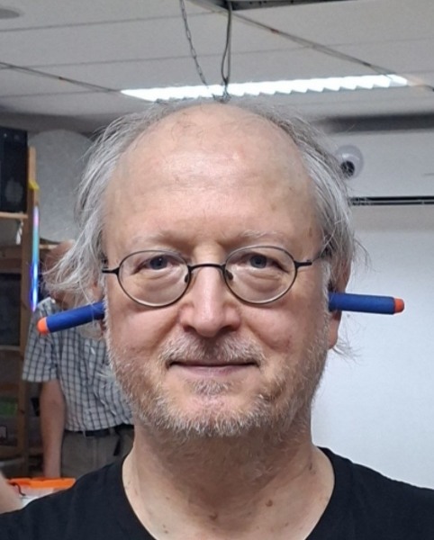
room where we usually get together. I forgot to bring my earplugs and ended up
using two Nerf darts
instead. The person who took the photo below called me 'fr-alien' in the
caption. We managed to lay the entire floor, but not all the items are in their
original places yet. I mainly focused on moving the cabinets and furniture,
disposing of the old laminate, and bringing the new laminate upstairs.
This months interesting links
Home
| July 2026
| September 2026


